So we have some idea of the modulation and frequency used by the alarm from our initial investigations. That’s only part of the picture really – but at least we know this isn’t using frequency hopping or anything too challenging.
Where to go from here? We take it apart! I’m not even going to power anything up in this instalment – just see what the system is made up of.
The alarm consists of several components…
- A solar powered bell box on the outside wall, with flashing LEDs, PP3 and 6V sealed lead-acid batteries, and a tamper switch.
- A keypad that mounts inside. This has 3 indicator LEDs, a tamper switch and is powered by a PP3 battery.
- PIR detectors. These have a single red indicator LED, tamper switch and are powered by a PP3 battery.
- Door contacts. These have a single red indicator LED, tamper switch, auxialliary contacts, and are powered by two CR2032 lithium batteries.
All use double sided PCBs, which appear well designed and are well made. Quality control stickers are on each board, as are small stickers on microcontrollers that look like firmware versions.
PIR
What do we see in here?
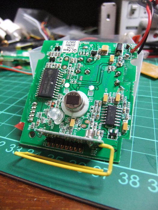
- An Elan EM78P418N microprocessor (PDF datasheet). These are essentially Chinese PIC clones that have one-time programmable (OTP) ROM in them. Generally OTP ROM is cheaper than EEPROM. I don’t expect I would have much luck reading the code out as. It might have in-circuit debugging, but the documentation is poor and I have had no luck with other Elan micros.
- An empty space for the crystal (X1), that indicates the Elan microprocessor is using an internal RC oscillator. This means that the microprocessor is not going to be doing anything requiring accurate timing, whether than be fast asynchronous protocols or waking at specific times. It does mean that at some point they considered using one – why would that be?
- An empty space for an 8-pin device, U1. There aren’t many 8 pin devices in use these days, only really serial EEPROMS. Pins 1-4 are common and likely ground. The Elan microprocessor has no EEPROM. Optional EEPROMs are interesting – usually the microprocessor will check for the presence of the chip, then check for a “programmed” flag. If the EEPROM is not programmed, it will write the default values and set the “programmed” flag. I might be able to add an EEPROM and see what it could store.
- A small RF daughterboard, with a TI CC1150 sub-1GHz transmitter (PDF datasheet) and 26MHz crystal. This is one of the CC11xx family – another well known member being the CC1110 SoC transceiver used in the GirlTech IM-ME. They are incredibly versatile and configurable. Importantly, we know that the PIR can only transmit, and not recieve. Many devices used a daughterboard for RF as I believe this can pass certification independent of the whole product and be easily re-used.
- The rest of the components are the power supply or PIR detector.
Door Contact
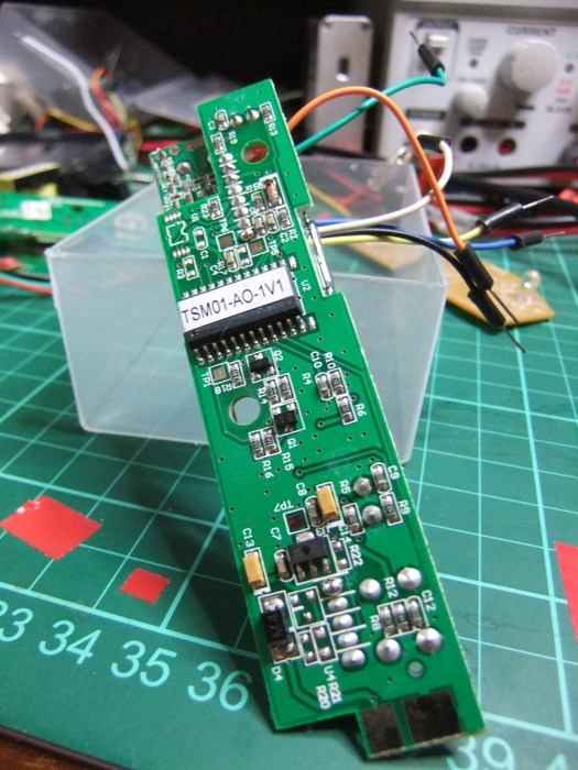
- Another Elan EM78P418N microprocessor. It makes sense to use the same technology across the range if possible.
- An empty space for a 8-pin SOIC again.
- No empty space for a crystal – it was never a consideration to use an external crystal for this board.
- The same RF daughterboard as in the PIR.
- The coloured wires are my addition!
Keypad
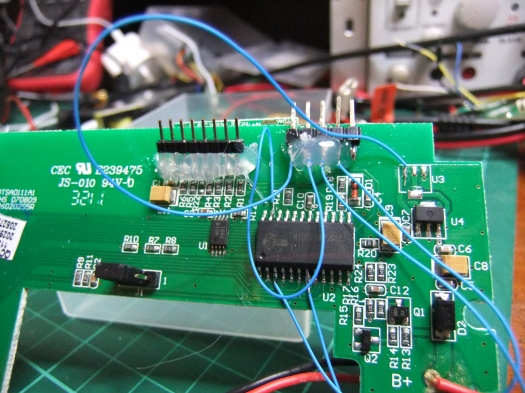
- Yet another Elan EM78P418N microprocessor.
- An 8-pin SOIC! HO18 08B1 – not much info on this. Pins 1-4 are grounded so I expect this to be a serial EEPROM.
- No empty space for a crystal.
- The same RF daughterboard again. This means the panel can only transmit, not receive. It is not aware of the state of other components,
- The pin headers and wires are my additions.
Bell box
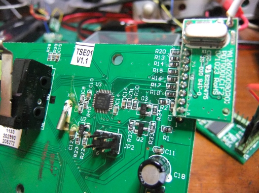
- An ATmega88 10MU122 microprocessor (PDF datasheet) – much more exciting (and much more familiar)! These use EEPROM and if the fuses are set right, I can read the EEPROM easily. I always find it interesting when products contain different processor architectures – maintaining two sets of code is an extra burden, so this choice is not made lightly.
- A cylindrical can crystal with no markings – often these are 32.768kHz crystals for timekeeping. The ATmega88 has a internal RC oscillator which can be quite accurately calibrated, but nowhere near as accurate as an external crystal. Interesting how this is the only component with an external crystal.
- No EEPROM or space for an EEPROM – probably because the ATmega88 has it built in unlike the Elan micros.
- A 6-pin populated pin header – Atmel’s in-circuit programming connector is 6-pin. I wouldn’t ever expect anyone to open this and reprogram it though – so why is the header on there?
- An RF daughterboard that is very similar – expect this time it is a CC1101 transceiver rather than just a transmitter. Interesting! This means that the only component of the alarm system that can receive and transmit is the bell box. This may have implications later.
Summary
So, for the RF side of things, all of the components are using the TI CC11xx chips. These support 2-FSK, fitting in with the findings in part 1. This is nice – I have worked with other systems using two or even three different RF frontends, and it makes things much more complex. We are also quite lucky – the CC11xx chips are very capable of frequency hopping spread spectrum at a high rate. We’re also lucky these aren’t the SoC versions as these have an AES encryption engine which makes strong encryption almost trivial.
Like Adam, I’d rather avoid RF. Luckily, the interface between the CC1101 and CC1150 is by SPI – I can simply sniff the connection between the RF daughterboard and microprocessor to see both the configuration and data. This is a privilege you don’t have if the CC1110 SoC is used – the transceiver and microprocessor are integrated with no easy way to access the config.
Next time, I will look at sniffing the SPI traffic between the microprocessors and RF boards.


Reverse engineering a wireless burglar alarm, part 3 | A connected ape