We need an antidote to the anti-code

In the last post, I briefly went over the process of reverse engineering the algorithm behind an anti-code generator for an alarm system.

It turned out that the algorithm was very simple indeed. For a given 5-digit numeric quote code, we can derive a 5-digit reset code using a “secret” 8-bit (256 possibilities) version number as a key. This has a lot in common with a keyed hash function or a message authentication code.

There are some pretty serious security implications with this mechanism.

5 digit numeric codes are never going to be strong

Even if I had to enter a pin at random, a 5-digit numeric code only has 100,000 options – I have a 1/100,000 chance of getting it right.

If we made this into a 5-digit hexadecimal code, we would now have a 1/1,048,576 chance – a factor of over 10 times less likely.

Up this to a 6-digit alphanumeric code, and it is now 1/2,176,782,336 – a factor of over 20,000 times less likely we could guess the code.

It doesn’t take many alterations to the limits on codes to make them much more secure.

For this reason it surprises me that alarms are still using 4-digit pins, but most internet forums insist on 8-character passwords with alphanumeric characters and punctuation.

The algorithm isn’t going to stay secret

There is no way to reliably protect a computer application from reverse engineering. If you can run it, at all, it is highly likely the operation can be observed and reversed. Relying on the secrecy of an algorithm or a key hidden within the software is not going to afford any level of security.

One we know the algorithm, the odds massively improve for an attacker

The algorithm takes a version number from 0-255. For a given quote code, I can try each version number, giving me a list of up to 256 potentially valid reset codes (sometimes, two version numbers will generate the same reset code).

If I enter a code from this list, I now have a 1/256 chance of getting it right. Not great compared to 1/100,000 for a purely random guess.

This is entirely due to the short version number used.

Given a quote/reset code, most of the time we can infer the version

It quickly became apparent that for most quote/reset pairs, there was only a single version number than could produce this pair. I’m awful at probability and decision maths, so I thought running a simulation would be better.

I like running simulations – generally when the number of simulations becomes large enough, the results tend towards the correct value. So I tried the following:

1. Generate a genuine quote/reset pair using a random quote.

2. Use a brute force method to see which version numbers can produce this pair

3. Record if more than one version number can produce this quote/reset pair.

I started doing this exhaustively. This would take a long time though… someone on the Crypto stack exchange answered my question with a neater, random simulation.

Pairs

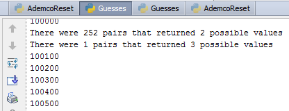
I ran this test over 20 million times. From this it turns out that 99.75% of quote/reset code pairs will directly tell me the version number. Most of the remaining 0.25% require yield two version numbers. A tiny number (<0.001%) yield more than four version numbers. You are almost certain to know the version number after two quote/reset pairs as a result.

What does this mean in the real world?

The version number is treated as the secret, and I am informed that this secret is often constant across an entire alarm company. All ADT alarms or all Modern Security Systems alarms may use the same version number to generate reset codes.

This means I could get hold of any quote/reset pair, infer the version number, and then use that later to generate my own anti-codes for any ADT alarm. I could get hold of these quote/reset pairs by going to an accomplice’s house with a ADT alarm system, or by eavesdropping on communications.

With that anti-code I could either reset a system presenting a quote code, or impersonate an alarm receiving centre (there are other speech based challenge-response requirements here to prove the caller is genuine, which are easily gamed I would imagine).

Conclusion

A 5-digit reset code using an 8-bit key is never going to be secure.

When computer passwords are 8 characters and 128-bit keys are the norm, this anti-code mechanism seems woefully inadequate.

Reversing an anti-code

A contact in the alarm industry recently asked if I could take a look at a quick reverse engineering job. I’m trying to gain some credibility with these guys, so I naturally accepted the challenge.

Many alarms have the concept of an “anti-code”. Your alarm will go off and you will find it saying something like this on the display:

CALL ARC

QUOTE 12345

The idea is then that you call the alarm receiving centre, quote 12345, they will input this into a PC application, get a reset code back, tell the customer, and then they can use this to reset the alarm. This means that you need to communicate with the alarm receiving centre to reset the alarm.

Alarm manufacturers provide their own applications to generate these codes. This particular manufacturer provides a 16-bit MS-DOS command line executable, which will refuse to run on modern PCs. This is a pain – it’s not easy to run (you need to use a DOS emulator like DOS-BOX) and it doesn’t allow for automation (it would be convenient to call a DLL from a web-based system, for example).

So I was asked if I could work out the algorithm for generating the unlock codes. x86 reverse engineering is not my forté, especially older stuff, but I thought i would have a quick go at it.

Turns out it was easier than expected! I find documenting reverse engineering incredibly difficult in a blog format, so I’ll just cover some of the key points.

Step 1: Observe the program

First things first, let’s get the program up and running. DOS-BOX is perfect for this kind of thing.

The program takes a 5 digit input and produces a 5 digit output. There is also a version number which can be input which varies from 0-255.

I spent a while playing around with the inputs. Sometimes things like this are so basic you can infer the operation (say, if it is XORing with a fixed key, flipping the order of some bits or similar). It didn’t look trivial, but it was plain to see that there were only two inputs – the input code and version. There was no concept of time or a sequence counter.

At this stage, I’m thinking it might be easiest to just create a lookup for every single pin and version. It would only be 2,560,000 entries (10,000 * 256). That’s a bit boring though, and I don’t have any idea how to simulate user input with DOS-BOX.

Step 2: Disassemble the program

To disassemble a program is to take the machine code and transform it into assembly language, which is marginally more readable.

There are some very powerful disassemblers out there these days – the most famous being IDA. The free version is a bit dated and limited, but it allowed me to quickly locate a few things.

An area of code that listens out for Q (quit) and V (version), along with limiting input characters from 0-9. Hex values in the normal ASCII range along with getch() calls are a giveaway.

Keyboard input
Another area of code appears to have two nested loops that go from 0-4. That would really strongly indicate that it is looping through the digits of the code.

Other areas of code add and subtract 0x30 from keyboard values – this is nearly always converting ASCII text numbers to integers (0x30 is 0, 0x31 is 1 etc. so 0x34 – 0x30 = 4)

Loops

A block of data, 256 items long from 0-9. Links in with the maximum value of the “version” above. Might just be an offset for indexing this data?

Data!
IDA’s real power is displaying the structure of the code – this can be a lot more telling than what the code does, especially for initial investigations.

Code structure
It’s still assembly language though, and I’m lazy…

Step 3: Decompile the program

Decompiling is converting machine code into a higher level language like C. It can’t recover things like variable names and data structures, but it does tend to give helpful results.

I used the free decompiler dcc to look at this program. I think because they are both quite old, and because dcc has signatures for the specific compiler used, it actually worked really well.

One procedure stood out – proc2, specifically this area of code:
DCC outputIt’s a bit meaningless at the moment, but it looks like it is two nested while loops, moving through some kind of data structure, summing the results and storing them. This is almost certainly the algorithm to generate the reset code.

Now, again, I could work through this all and find out what all the auto named variables are (i.e. change loc4 to “i” and loc5 to “ptrVector”. Or I could step through the code in a debugger and not have to bother…

Step 4: Run the code in a debugger

A debugger allows you to interrupt execution of code and step through the instructions being carried out. It’s generally of more use when you have the source code, but it is still a helpful tool. DOS-BOX can be run in debug mode and a text file generated containing the sequence of assembly instructions along with the current registers and what is being written and read from them. It’s heavy going, but combined with IDA and the output from DCC, it’s actually quite easy to work out what is going on!

Step 5: Write code to emulate the behaviour

Shortly after, I had an idea how the algorithm worked. Rather than work it through by hand, I knocked up a quick Python program to emulate the behaviour.The first cut didn’t quite work, but a few debug statements and a couple of tweaks later, and I was mirroring the operation of the original program.

Overall, it was only a few hours work, and I’m not really up on x86 at all.

I’m not releasing the algorithm or the software, as it could be perceived as a threat. In the next post, I am going to discuss some of my security concerns around the idea of an anti-code and this specific implementation.

What’s inside a WebWayOne SPT?

I managed to find a reasonable resolution image of a WebWayOne SPT (supervised premises transceiver, the device that communicates with the ARC (alarm receiving centre)). Just some quick notes about what is on it.

Annotated PCB

Annotated PCB

The Coldfire processors have a hardware encryption acceleration engine on them, which suggests that some fairly heavy duty encryption is happening.

Tomographic motion detection

Typical alarms use PIR (passive infrared), microwave or ultrasound detectors for motion detection. PIR are by far the most common type of detector – they work by detecting changes in infrared emitted by warm bodies. They are cheap, very reliable, and actually quite hard to beat.

Laser break beams are only really seen in films, though simple active infra-red break beams are often used on scaffolding alarms.

The problem with all of these is that they cannot see through objects. A common method of circumventing PIR detectors is to “mask” them – you either cover them  using paint (or another infrared opaque coating) or simply put something like a box in front of them. Higher security systems have “anti-masking” detectors which use an active element to check that their view has not been masked.

It can mean that complex, cluttered, or continually changing spaces need a lot of PIRs to be adequately covered.

Step in a new type of motion detection – tomographic motion detection. This sounds really clever and innovative. You might have heard of tomography from the medical world – CT scan stands for computerised tomography. It means “imaging by cross section”. Xandem have come to the market with a new detector that uses 2.4GHz radio signals to detector motion in a space.

A group of wireless nodes form a mesh of connections, as shown in this image from the patent:

Mesh network

Mesh network

Each one of those lines represents a radio path. The system uses 2.4GHz signals, the same as with WiFi or Bluetooth. These are heavily attenuated by anything containing water – such as the human body. A human body placed in the radio path of any two nodes will reduce the received signal strength (RSS).

By carefully measuring the RSS from each node to each other and doing some clever processing, you should be able to build up an image of what the area usually looks like. Any significant disturbance would signal an alarm. Hence, motion of a human body can be detected.

This would work through walls, shelves, furniture and so on – as long as the signal strength is attenuated too much.

This is clever stuff. Very easy to fit (though you do need power to each node), and probably very hard to beat. It is expensive though.

For those interested, here is a link to the patent:

https://docs.google.com/viewer?url=patentimages.storage.googleapis.com/pdfs/US20120146788.pdf

And I have pulled a picture of the PCB from the FCC report on it:

PCB

PCB

The markings on the main IC are not visible, but based on the frequency, size of the package, crystal frequency, crystal connections and antenna connections, this is a TI CC2540 RF SoC – a brother to the CC1110 RF SoC, using an 8051 core connected to a RF transceiver.

Interestingly there is a micro-USB and debugging connector on the board as well!

Why am I hacking your alarm?

Since I’ve started posting about alarm systems, a number of people have questioned by motives. I can understand why – these are security products and I can see how many people would think poking around inside them is “dodgy”.

I’d say I have three main drivers:
  1. I love taking electronics apart and working out how they work. It’s much more challenging and interesting when someone has actively tried to stop you doing this – alarms are an ideal target because of this. I initially bought an alarm hoping it would contain a rolling code system for me to reverse, but it turned out to be far too basic. In the end I found a massive string of vulnerabilities anyway.
  2. I find security as a concept fascinating, from locks through access systems through human factors. I love how the perception of security is so often different to the reality. One of my current drivers is that I think the security economics around alarms is totally broken – it’s driven by outdated , rigid standards and insurance rather than actual security.
  3. I used to watch Bugs on BBC1 each week religiously so I spent my teenage years watching people break into high-tech buildings using fancy electronics. Whilst I’m not doing the actual breaking in, having the means to disable alarm systems and bypass access controls is fun and something I never thought would be possible to do.

It swings both ways, especially for RF comms

In a few of the previous posts, I’ve discussed some principles used in the radio communications in alarms. I’ve mentioned that some features are harder to implement well using one-way radios. What is the difference between one-way and two-way? What practical difference will it make?

Radio communications can be one-way or two-way, depending on how they have been designed.

A one-way system has a transmitter in each of the detectors and a receiver in the panel. This means that the detectors can send signals to the panel, but the panel cannot send signals to the detectors.

In a two-way system, each component has both a transmitter and receiver. This means that the detectors are now capable of receiving a signal from the panel.

It is fairly normal for the two-way systems to use a combined transmitter and receiver called a “transceiver”. Whilst not a strict limitation, most of these transceivers can only transmit or receive at any given moment in time (this is called half duplex). They can switch from receive to transmit very quickly, so from a user perspective they look like they are transmitting and receiving at the same time.

Most older systems use one-way radio. I suspect this is because there were not easy to use, cheap integrated RF transceivers available 10 or 20 years ago. Often they will use a simple AM transmitter built from discrete components or one of the very old remote control ICs that require an 8-bit address (these are common in wirelessly controlled mains sockets still).

A lot of newer systems use two-way radio. They will use one of the modern integrated RF transceivers like the TI CCxxxx, Si4432, or any of the Nordic Semi products. These do all of the hard RF work (and even a lot of the packet handling and encoding, sometimes even encryption) for you, and are controlled using a simple digital serial protocol. They are very cheap and versatile.

What are the practical limitations of one-way radios?

There are an awful lot of them – too many to list really. Let’s cover a few really key ones

Detectors have no idea if the system is armed or not

There is no way for a detector to know if the system is armed or not as it cannot receive any information.

This means that they always have to behave as if the system was armed. This behaviour has to be a balance of responding to alarms quickly vs preserving battery life. This trade-off is often accomplished by holding-off alarm detection for a period of a few minutes after an alarm has been raised.

It also means that they try to send supervisory “OK” status messages as infrequently as possible – and by standards, this can be up to 240 minutes.

This has practical implications for how responsive an alarm system can be.

The panel cannot ping the detectors when it is armed

Two-way panels all actively check the presence and status of detectors at the moment the system is armed. If any are in tamper, contacts open, detectors missing, or batteries low, the user will be warned (and possibly, arming the alarm is not allowed). This is very similar to how a wired system works.

One-way systems need to rely on the last alarm or status message received. They could be from a long time prior and could be out of date.

Rolling code and encryption is much harder to do well

In a previous post, I discussed how rolling code systems can’t just accept the next code in the sequence – they need to accept codes over a wide window, possibly the next 256 valid codes. This is because the transmission is not guaranteed to be received and the transmitter hops forwards regardless.

With a two way system, this window can be avoided. The keyfob can continue to send the same code in the sequence until the panel sends a message back saying that it has been received (this is a simple explanation of how it could work, pure rolling code is rare in two-way systems).

Alongside this, one-way radio makes exchanging keys in encryption systems difficult. A similar concept to the window of valid codes needs to be used to ensure that transmissions are received correctly after a key changes. For this reason, encryption keys in one-way systems are most often fixed (though they can be exchanged during the initial pairing).

Conceptually, it’s exactly the same as two people trying to communicate reliably with each other, where one of them can only speak and the other only listen. There’s also a 2 year old in the room who won’t shut up (interference), and another guy who is actively trying to make sure everything goes wrong (a malicious attacker).

This raises another interesting aside – alarm systems always need to find a balance between security and reliability of communications. There is little use in ensuring that communications are completely secure if it means alarm messages to do make it through.

Security devices and product differentiation

An interesting subject has come up on the TSI forumsproduct differentiation in relation to encryption and security in alarm signalling systems.

As with alarms, there are different grades of signalling devices. These go from grade 1 (low risk, doesn’t seem to be used much or at all) to grade 4 (high risk, banks, jewellers). It’s common for the signalling device to be a higher grade than the alarm system, although this is not mandated.

Grade 4 requires encryption, protection from message substitution and replay etc. One provider, WebWayOne has built a system that uses several proven technologies like AES-128 and other widely known cryptographic fundamentals.

One of WebWayOne’s representatives said on the forum:

“Once these techniques are in place they may as well be deployed across all grades if system, it makes no sense not to.”

This is an awesome attitude to have and, to me, signals that these guys have actually understood the challenges in implementing a secure protocol. They are not weakening lower grade systems by weakening the cryptography and protocol.

Why do I think this is sound reasoning? It’s probably easier to argue why weakening the cryptography and protocol is not a good idea – here are some ways I have seen it done in other systems using cryptography (not alarm signalling systems – I am extending my reasoning from other products to apply to them).

Reducing key-length

Some products differentiate different grades of security by reducing key length. This tends to be a bad idea.

Practically all cryptographic techniques are vulnerable to brute-force attacks – it really is just trying every single key, one by one. It’s accepted at the moment that 40, 56 and 64 bit keys are not long enough to protect against brute-force attacks. 112 bit (twice 56, used in keying method 2 in triple DES) and 128 bit are currently long enough to protect against brute-force attacks. This will change in the future, but we are safe for a good few years yet.

Anything above 128 bits is therefore deemed wasteful – your highest grade product could use 128 bits and be secure. You could alter your lower grade product to use 64 bit keys. To the lay person, you might think that this would take half the time to brute force –  but it is actually easier by a factor of 2^64 (18446744073709551616 times easier).

You could offer 127 bit encryption – this would take half the time to crack. But what would be the point? It would be product differentiation for no reason, and implementing a custom key length nearly always means you are “rolling your own” and will make mistakes.

Altering the protocol

Changing the protocol in anyway would also be an odd way to differentiate a lower grade.

Outside of key length, most aspects of a protocol are either a binary secure/not secure. You can’t offer 50% of message authentication. You can’t offer 50% of a secure means of key exchange. They are either present and secure, present and insecure, or not present at all.

If any aspect of a secure protocol is deemed insecure, it’s highly likely that the whole thing will fall apart. This isn’t always the case, but it’s fairly usual to see a theoretical vulnerability against a single part (say, the message authentication) turn into a full blown practical exploit against the whole thing. This means you need to tread carefully when trying to artificially weaken a protocol.

The hardware is there anyway

Signaling systems don’t have the same constraints as wireless detectors. They have plentiful power and space, which affords the use of comparatively powerful hardware.

Most detectors use 8-bit microcontrollers like the PIC, ATmega, or 8051 built into the CC1110. They run using slow clock rates (this lowers power consumption) and have limited RAM and register space. Implementing full blown cryptographic schemes in these is not easy, especially when you move up to something like RSA with 1024 bit keys (RSA is public key cryptography, where you need a much longer key to be secure than with symmetric cryptography like AES).

I have not seen inside any IP signaling devices, but I would wager that they use modern, powerful 32-bit processors like the ARM, with plentiful RAM and fast clocks. There are cryptographic libraries already available on these processors that allow you to easily build a secure protocol.

This hardware is likely the same across all grades. Again, it just makes no sense to build a lower grade system using different hardware to artificially constrain it.

Testing

Properly pen testing products, as compared to “test house” testing to standards, is a time consuming, expensive and highly skilled job. Having two distinct products, even if they only different slightly in hardware and software, would really require two distinct pen tests to be performed. This is cost you do not need to bear. Test the grade 4 product, use the same hardware and software for grade 2, and you have just tested both at the same time.

Differentiate on the tangible aspects

When it comes down to it, all of this doesn’t really matter to the customer. They just want something secure. So differentiate on the tangible things – how long the signalling takes to report issues, and the response to alarms.

Encryption is only part of the solution

So, in the previous two posts I have covered:

And talked about how, although they are useful techniques to make an alarm better, they need to be implemented correctly.

Now, I am going to briefly cover encryption, and how it can go wrong.

What is encryption?

At a very basic level, encrypting something is encoding a message in a way which means an eavesdropper cannot determine the contents of the message.

There are many techniques – the one most familiar to people is a substitution cipher, where each letter is substituted for another.

In the real world, encryption uses more advanced techniques than this. Some encryption techniques are, to all intents and purposes, impossible to crack – unless you know the secret key, you are not going to find out what is in the message.

Sounds great! Where do I sign up? Many alarm manufacturers use encryption, and many don’t do it quite right.

Designing a good encryption scheme is hard

A famous saying is:

“Anyone can invent an encryption algorithm they themselves can’t break; it’s much harder to invent one that no one else can break”

Time and time again, custom built encryption algorithms have been broken.

Again, I’m sure there is a more concise saying about this, but I subscribe to this:

For a defender to succeed, he must have a 100% success rate against multiple attacks and attackers.

For an attacker to succeed, he only needs to succeed once.

What’s the solution to this:

  1. Use something off-the-shelf. There are mathematicians and developers who only develop encryption. Use their skills, don’t try to use your own.
  2. Open your code up – no encryption algorithm or implementation should be weakened by an attacker seeing the code. So open it up and let other people tell you the problems!

Encryption is often good in theory and fails in the implementation

Very closely linked to the above point – even if you use something off the shelf, make sure you use it right!

Common mistakes are:

  • Leaking key material by XORing the key with a constant padding value (in a previous post!)
  • Building a really strong encryption scheme but then failing to exchange the key in a secure way (i.e. you show everyone the key!)

Encryption by itself does not stop replay attacks

If the message “disarm the system” becomes “fodst, yjr dudyr,” when encrypted, there may be no easy way for the attacker to decode that message. Indeed, there would be no easy way for him to encode that message unless he had the key.

This may not matter though. You can infer what the message contains based on timing (the homeowner has just arrived, and pressed the disarm button), and replay the encrypted packet alone. You need to combine encryption with other techniques to ensure integrity and protect against replays.

Using a fixed key across all products

Again, this is partly the result of using a one-way radio system. Before the detector and panel can communicate, they need to perform key exchange, so that they both know the secret key. There are a few options here:

  1. You can send the key in the clear when paired and hope no one is listening.
  2. You can use a secure method of exchanging keys (like public key cryptography)
  3. You can program the key in during manufacture

Method 3 is attractive. On paper, your system is “encrypted” – you could even claim AES-128 encryption. But if that key is constant across every detector and every panel you sell, you have a problem. Why is this?

Firstly, you can never really assume that your code is safe. Whilst most modern microprocessors have some means of protecting code, this is by no means fail-safe. Sometimes designers forget to set the lock bits (well, quite often in fact), and the code can just be read out. Some PIC processors are vulnerable to a simple attack where you can recover 75% of the code from one device, and the remaining 25% from another (one manufacturer’s detectors have this issue). If you want to go further, you can decapsulate the microcontroller and read one-time-programmable memory visually – this is possible in the real world.

Secondly, it is sometimes the case that the alarm architecture means that I don’t need to know this key. Some alarms have an RF SoC performing all encryption – the main microcontroller just passes it simple unencrypted data. I can decouple the RF SoC and send my own, unencrypted data, and let the SoC do the hard work for me.

Thirdly, manufacturers offer firmware upgrades for download. These can contain the secret key material. It’s often easy to find – key material should look very random (more random than normal code). I have a simple tool to scan a file and graph entropy. It’s fairly easy to find key material using this, especially if you know how long the key is.

Using too short a key

One method of breaking encryption is to just try every single key and hope for the best – this is called “brute forcing“.

If the key is short, this process can be very quick.

Each time I add a single bit to a key, I double how many possibilities there are. A 1-bit key has 2, a 2-bit key 4, 3-bit has 8. This rapidly hits very large numbers – even at 32-bit we have 4294967296 keys. But modern computers are very, very fast – checking 100,000 keys a second is possible. That 32-bit key would fall in under 12 hours.

So key length has a big impact on how long it takes to perform this process. It’s now pretty much assumed a key length of 64-bits and under is too short to protect against brute forcing. But DES and other encryption methods still support 40-bit and 56-bit keys. If the option is there, people will take it.

Conclusion

Encryption is important in a wireless protocol if you want it to be genuinely secure – but it is only part of picture. If implemented badly, it can add little security and decrease reliability and usability.

Keep rolling, rolling, rolling

In the last post about technologies used in alarms, I discussed the use of spread spectrum. Another really common keyword seen on marketing material is “rolling code”. What is it, why is it used, and what problems are there with it?

Why?

A wireless alarm system might send a signal from a keyfob to the panel to say “disarm the system”. If the content of this packet does not change in any way from time to time, we could simply record this packet and replay it at a later time.

This is commonly called a replay attack. There are alarm systems available that are vulnerable to this attack – the older Yale Wireless Alarm systems (434MHz ones) and Friedland SL series are examples. There are “Universal cloning remotes” on eBay for less than £5 that will clone any alarm using 434MHz OOK signalling. You can also use an Arduino and cheap receiver to listen out for signals and store them for later replay.

It is desirable to have a means of stopping these replay attacks from happening.

There is nothing in the EN50131-5-3 specification that means a grade 2 alarm needs any protection against these attacks. Most newer alarms do however have some protection.

How?

The attack is possible because the signal doesn’t ever change – it is always “disarm the system”.

To protect against a pure replay attack, we just need to add something that changes each time the signal is sent. How about the time? “disarm the system 21:22:32 26/04/2013”

This works. There is now no way for me to record a packet and use it again later.

But a really malicious attacker could work out how to take a packet recorded earlier, modify the time, and replay it.

This is where rolling code comes into play – instead of appending the time, we add a code to the packet. This code changes each time a packet is sent. The receiver and transmitter have agreed how this code will change – generally using a psuedo-random number generator.

The packet now becomes “disarm the system 204389473692”, the next time it will be “disarm the system 937459384322” and so on.

The sequence of this codes is essentially random to an observer, and the code is long enough that it makes guessing the next one very difficult.

Unlike spread spectrum, this sequence is generally extremely long in small systems.

Keeloq is a proprietary implementation of a rolling code protocol, often used in car keyless entry systems. The rolling code is 32-bit, which essentially means it is impossible for someone to guess the next code.

Keeloq does have weaknesses. The major one is that it is possible to recover the key used to seed the random number generator. Once you have this, it is far easier to guess the next code. It’s still very challenging though.

What issues are there with rolling code?

Again, the devil is in the detail. Rolling code is a sound principal – but it must be implemented correctly.

Predictable codes

The whole thing falls over if someone can guess the sequence of codes you are using. There are a number of ways that this can happen.

If your code is short (say, 8bits), the an attacker has a 1/256 chance of getting the next code correct if he chooses randomly. If your code is long (say, 32 bits), then it is 1/4294967296. Whatever method you are using to guess the codes, you can clearly see that the longer the code, the harder it will be.

A good pseudo-random number generator (PRNG) can be seeded – you give it a key which determines how it will hop. It shouldn’t matter what the algorithm is or if the attacker knows the algorithm, as long as they don’t know the seed, they shouldn’t be able to predict the sequence. Unfortunately, many products either used a fixed seed across all products (this makes protocol design, especially with a one-way radio, much easier) or the algorithm is bad.

How can the algorithm be bad? Say we have a PRNG with this output when seeded with “1”:

7, 3, 4, 1, 3, 6, 1, 3, 2

If I were to seed it with “2”, the output should be completely different:

8, 3, 3, 2, 7, 1, 5, 3, 1

But some systems simply use the seed to skip some of the output i.e. with a seed of “2”:

3, 4, 1, 3, 6, 1, 3, 2, 8

Notice this is just the first sequence shifted along one digit!

If I know the entire sequence, then all I need to do is gather a few packets and I can work out where we are in the sequence. The number of packets I need varies, but with a poor PRNG or short code, it’s not very many!

Worse still, some “rolling code” systems use a code like:

1, 2, 3, 4, 5, 6, 7, 8, 9, 10

Whilst this might protect against casual replay attacks, it is not hard for an attacker to guess the next number.

Limitations with one-way radios

If your keyfob can transmit but not receive, there is a small problem. Each time it transmits, the code rolls forward. There is no guarantee that the receiver will hear the transmission.

This means that the transmitter’s code can be further ahead in the sequence than the receiver. This needs to be taken account of – what happens if you are idly pressing the disarm button in your pocket whilst waiting for the bus?

Most systems deal with this by checking for a valid code over a “window” of acceptable values. This could, say, be the next 256 codes. This has an interesting effect on guessing. If I have a 16 bit code, there are 65,536 possibilities. If the window was only 1 long, I would have a 1/65,536 chance of randomly guessing the code. If the window is 256 long, we reduce this by a factor of 256 – to 1/256. That’s a big difference.

Message substitution

A very simple rolling code implementation just appends the pseudo-random code onto the message i.e. “disarm the system 878463098273”

There is no link between the message (“disarm the system”) and the code (“878463098273”).

This means we can change the message and use the same code, providing that the receiver hasn’t received the code.

How could this be done? I’ll give one possible attack.

When you press “arm the system” on the keyfob, it will actually send more than one packet, to ensure that the receiver gets the message. We have something like:

arm the system 736474747363

arm the system 093219457437

arm the system 384838738383

arm the system 732878476655

If I am in the position to jam the receiver, but still receive the genuine packet, I can do the following:

1. Record all 4 packets.

2. Immediately replay the first two to arm the alarm so the user does not see an issue:

arm the system 736474747363

arm the system 093219457437

3. Hold onto the last two packets.

4. Change the messages on the second two packets to:

disarm the system 384838738383

disarm the system 732878476655

And bang, we have disarmed the system.

Replay attacks still work

As long as the packet never reaches the receiver, we can still grab a transmission from a keyfob and use it later. This means someone could press the disarm button on your keyfob whilst you are away from the house (say, when you pass your keys to the checkout assistant to scan your loyalty card), and then replay it later.

Conclusion

Rolling code, again, is a good idea, and if implemented well, can protect against a lot of attacks. Many systems do not implement it well though – the above vulnerabilities can be found in real world alarm systems.

A much more robust solution is to use timestamps in the messages and then use encryption and a message authentication code.

If anyone is interested, Atmel have a really good app note on implementing a secure algorithm with one-way radios.

The ups and downs and ins and outs of spread spectrum

It’s becoming increasingly common to see the terms “spread spectrum“, “frequency hopping” or “FHSS” on the spec speets for wireless alarm systems.

The question is, what does it mean and how does it improve a wireless alarm system?

We might as well start with the wikipedia definition:

Frequency-hopping spread spectrum (FHSS) is a method of transmitting radio signals by rapidly switching a carrier among many frequency channels, using a pseudorandom sequence known to both transmitter and receiver.

A diagram is a clear way of showing this:

Time vs channel

Time vs channel

This is a really basic example with only 5 channels. The channel changes for each time slot, and the hopping pattern is a rather predictable 4, 1, 5, 2 3. Both the transmitter and receiver know this hopping pattern and hop at the same interval.

Practical systems tend to use large numbers of channels (50 upwards) and hop frequently (hundreds of times a second).

This technique is used by Bluetooth and other technologies.

There is another form of spread spectrum called Direct Sequence Spread Spectrum, where the hops are faster than the data rate. This is rarely used in small embedded systems, but is used in WiFi.

What are the advantages of FHSS?

Resistance to jamming and interference

The most obvious advantage is that narrowband interference or jamming (jamming is really just intentional interference) will only cause a problem for one of the channels, so a signal can still make it through.

Jamming, I hope you like jamming too

Jamming, I hope you like jamming too

In the image above, there is interference on channel 2. None of the signal on channel 2 will be received, but all of the other channels are still fine. Even if you continue to use channel 2, 80% of packets will make it through.

Resistance to eavesdropping

At least at a superficial level, you could conceive that an eavesdropper would have to know the hopping pattern to be able to listen it to a FHSS signal. For this reason, some think the FHSS provides added security.

Transmitting with higher power

This is not intrinsic to the technique of FHSS, it is more related to regulatory requirements. A big problem with most ISM band radio systems is contention for channel access. The most common technique to avoid problems (without using spread spectrum) is to limit the duty cycle to 1% or below. This gives other devices a chance to use the channel.

FHSS avoids this issue as you are only using one of a number of channels in a group. Multiple devices can be using the same group of channels and it is unlikely they will want to use the same channel at the same time. Contention is less of an issue for this reason.

This is turn means that more devices can operate in a given area. The area a transmitter operates in is defined by it’s output power – a higher power can transmit further.

The lower chance of contention means that FHSS devices are allowed to transmit with a higher power, and hence tend to have longer range.

What are the problems?

It sounds like FHSS is a great idea. But, as always, the devil is in the detail.

You cannot rely on FHSS to provide protection from eavesdropping

If we take a practical example of one alarm system – this hops over 50 frequencies in the US version (which is the FCC’s minimum number) at a rate of 64 hops per second. This might sound fast, but it really isn’t.

The CC1110 RF SoC has built in support for FHSS. Using a technique whereby you pre-calibrate the frequency synthesiser, a hop time of ~75uS can easily be achieved. You can essentially turn it into a scanner – scanning all 50 frequencies as quickly as you can. This takes 3.75ms, a lot less than the dwell time of 15.625ms (1/64).

I might not be able to receive all of the packet – I’m going to miss at least some of the start of it – but I can receive some.

More to the point, I can record the hopping pattern. The design of most wireless systems means that this will never change.

The CCxxxx chips are used in a lot of alarm systems – from the low-end Friedland SL series to the high-end Texecom Ricochet. When they are used in alarm systems, they tend to be used conservatively – they need to work correctly all of the time. As a reverse engineer and hacker, I can push these chips to their limits and just hope that they work well enough to meet my goals once.

The same system mentioned above is sold in the UK but only hops over 4 frequencies. I don’t think this even meets regulatory requirements (another downside to self-certification), but it provides no protection against eavesdropping or even interference.

Predictable or simple pseudo-random hopping patterns

Both transmitter and receiver need to decide on a hopping pattern ahead of time. There are a number of techniques used to do this – you can store a predefined pattern in memory, or generate one using built in hardware or software.

A cold hard fact of pseudo-random number generation though is that the pattern will repeat at some point. This could be after 127bits or 32767bits or anything really depending on how it is implemented. Small embedded systems tend to use patterns that repeat after short periods though – PN9 (i.e. 511bits) is common.

This means it is entirely feasible to record the hopping pattern. It’s very likely this pattern will be re-used.

Some systems make it possible to look at the firmware and see the code that generates the hopping pattern.

Sequences are the same across all equipment

It’s hard to make every single device “custom”. This isn’t really a manufacturing concern – most devices are programmed at some point with a unique serial number. It’s more a protocol design issue – communicating a secret between devices ahead of time is hard work, especially on a one-way radio system. It’s also hard to work with 10 different transmitters using 10 different hopping patterns.

This means all detectors and all panels across every system made might use the same sequence. It only takes a small amount of effort for an attacker to determine this sequence and reuse it time and time again.

FHSS is complicated by other functionality

One of the advantages of FHSS is resistance to interference. As shown in the diagram above, if channel 2 is interfered with, we will only lose 20% of packets.

This is still a 20% packet loss – if other layers of the protocol aren’t designed to take account of this, it could totally cripple the system.

For this reason, many FHSS systems also employ adaptive frequency agility (AFA). If they detect a problem on a given channel, that channel will be taken out of use.

Adaptive frequency agility

Adaptive frequency agility

How could this be a problem? Well, how long do I take that channel out of use for? What happens if more than 50% of my channels are taken out of use? There needs to be some kind of mechanism to bring the channels back into use at some point.

The design of AFA algorithms is complex, and mistakes are made. It can be possible to game them into a state where they believe that most channels are unusable. A parallel to this is mesh networking routing algorithms  – you can sometimes game the system into believing there are no valid routes with only a few carefully crafted packets.

Conclusion

Whilst FHSS is a useful technique to improve interference and jamming immunity, it should never be relied on for security – that is what encryption and MAC is for.